Comparing Energy Savings in IES
The building we modelled
We are often asked what IES shows for natural ventilation
and alternative ventilation strategies. The short answer is the e-stack system provides significant energy savings. But don’t take our word for it let us help you to model your classroom.
We have modelled a typical Manchester classroom.
We’ve taken the middle floor classroom which is
North facing and therefore gets the least solar gain.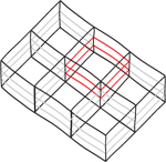
The parameters of the classroom are:
Floor Area: 64m2
Height: 3m
Glazing Area: 9.6m2
Occupancy: 32 people 9am-5pm weekdays with a lunch break
Heating Setpoint: 18°C 8am-5pm weekdays
Lighting Load: 12W/m2
Additional Equipment: 1000W
The simulations have been run on the Manchester TRY weather file but you can run a simulation on any weather file by downloading the IES files from the menu on the right.
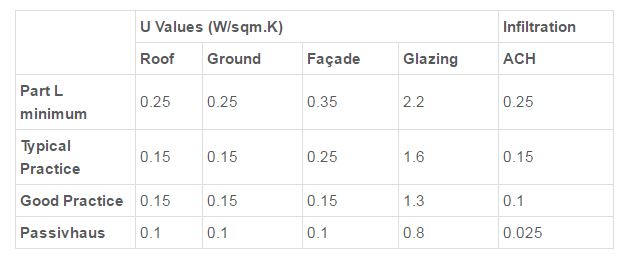
Similarly we have run the simulations for a building with good practice U-values and infiltration rates. The U-values we have used are in the table, but you can tailor the model to have constructions exactly like your building. We’ve also modelled a room with an exposed concrete soffit which acts as thermal mass, but you can change this too.
We have modelled four different ventilation strategies:
e-stack
- Conventional Natural Ventilation
- Mechanical Ventilation with Heat Recovery (MVHR)
- MVHR with opening windows in the summertime
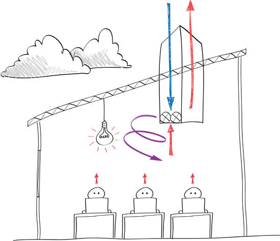
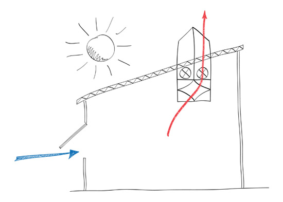
The e-stack natural ventilation system uses technology based on a University of Cambridge patent which is designed to ensure a minimum rate of air change between a building and the exterior in Winter to comply with Part F of the building regulations, whilst minimizing the heating energy required.This is achieved by mixing the incoming cold fresh air in Winter with hot interior air prior to it reaching the occupants. The system ensures that the air quality remains very high but also that the building is totally comfortable to avoid the risk of cold draughts which are often associated with natural ventilation systems.
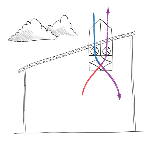
In warmer weather the system typically operates with higher ventilation flow rates in order to minimize the risk of overheating, although it can be used in conjunction with thermally massive building types to exploit the benefits of passive night-cooling in which case lower ventilation rates are again used.
How we’ve modelled this in IES
When calculating the energy associated with ventilation we think about 2 components
- The energy required to heat the space
- The fan power required to drive the ventilation. For e-stack ventilation, in the winter (when external temperature is less than 16°C) we require fan power to mix the cold incoming air with warm room air. This fan power is 100W when providing minimum ventilation of 5l/s/person and 150W when we are required to boost ventilation to prevent overheating. We also require heating in the space when external temperatures are very low, such that room temperature drops below 18°C. In the summer (when external temperature is greater than 16°C) e-stack ventilation requires no fan power because, when we open the low level windows in the room we can rely on natural buoyancy to drive the ventilation.
Through the use of IES we want to obtain the heating requirement of the room and the flow rates which are required to keep the room at an acceptable temperature during the wintertime (ie. the flow rates which will require fan power).
In our model, e-stack ventilation is modelled as a mechanical ventilation system with no heat recovery. The way that IES deals with the cold incoming air is as part of a heat balance with all of the heat gains within the space, and therefore this in analogous to the way in which e-stack uses the excess heat in the room. The mechanical system is set to provide 5l/s/person (ie. 160l/s) during occupied hours. Boost ventilation is provided by specifying a ‘natural ventilation’ flow rate which is assigned a profile such that it operates when room temperature exceeds 25°C during the occupied day. In our model the flow rate is set a 150l/s but this should be altered to suit your building, so that overheating is prevented – meaning that we can meet the BB101 standard of no more than 120 hours greater than 28°C.
Conventional Natural Ventilation

How conventional natural ventilation works
In the summertime we will assume that natural ventilation is carried out through the use of opening windows at low level and a passive stack or opening window at high level. Normally the low level windows will be inlets and the high level openings will be outlets.
In order to provide sufficient ventilation in the wintertime to maintain fresh air levels and prevent overheating, we will continue to use this upwards displacement ventilation strategy. This means that by opening windows we are risking subjecting the occupants to cold draughts and therefore we will need to preheat the incoming air. This preheat will have to take place for any occupied hours which are less than 16°C.
How we’ve modelled this in IES
When calculating the energy associated with ventilation we think about 2 components
- The energy required to heat the space
- The fan power required to drive the ventilation.For conventional natural ventilation, we require no fan power all year round.
In the wintertime (when external temperature is less than 16°C) we need to preheat the incoming air to 16°C before supplying it to the room. We also need to supply space heating to the room, in case it is required for morning preheat to achieve a setpoint of 18°C in the classroom.
Through the use of IES we want to obtain the amount of preheating energy required to achieve the target temperature for incoming cold air. We also want to ensure that we are supplying enough air to the space to prevent overheating in accordance with BB101.
In our model, natural ventilation is modelled as a mechanical ventilation system. This is the easiest way to force IES to model a preheat on incoming air! We will however not attribute any fan power to supply and extract the air from the space. The mechanical system is set to provide 5l/s/person (ie. 160l/s) during occupied hours, but incorporates a boost which is assigned a profile such that it operates when room temperature exceeds 25°C during the occupied day. In our model the boost flow rate is set at 150l/s but this should be altered to suit your building, so that overheating is prevented – meaning that we can meet the BB101 standard of no more than 28 hours greater than 28°C.
MVHR
How mechanical ventilation with heat recovery
works
The mechanical ventilation system supplies fresh air at minimum ventilation rate during the wintertime and exceeds minimum ventilation when it is necessary to prevent overheating.
The heat exchanger is set at 50% efficiency, meaning that this is the maximum amount of heat which can be recovered. However the supply air is also controlled so that its temperature does not make the room exceed 21°C and therefore the heat exchanger has a bypass function which means that we can use a smaller percentage of heat recovery or no heat recovery at all if the incoming air is of a sufficient temperature.
How we’ve modelled this in IES
When calculating the energy associated with ventilation we think about 2 components:
- The energy required to heat the space
- The fan power required to drive the ventilation.For mechanical ventilation we will operate in the same way throughout the whole occupied year. The mechanical system is set to provide minimum ventilation of 5l/s/person (ie. 160l/s) during occupied hours. Boost ventilation is provided by specifying a ‘natural ventilation’ flow rate which is assigned a profile such that it operates when room temperature exceeds 25°C during the occupied day. In our model the flow rate is set at 150l/s but this should be altered to suit your building, so that overheating is prevented – meaning that we can meet the BB101 standard of no more than 120 hours greater than 28°C. Heating is provided to the room through radiators in the space which are set to maintain a room temperature of 18°C during heating hours.
Through the use of IES we want to obtain the heating requirement of the room and the flow rates which are required to keep the room at an acceptable temperature which is the sum of the minimum ventilation rate, plus any boost ventilation required.
The flow rates will then we translated into a fan power required to achieve the rate. This is done by using a typical fan curve for a range of MVHR systems, where minimum ventilation of 160l/s requires around 160W and the fan power will never exceed 500W, which we have set as a fixed maximum inspite of the flow rate.
MVHR with Opening windows
How mechanical ventilation with heat recovery and opening windows works
In some buildings a MVHR system is specified which will be used in the wintertime to reduce the amount of heating which is required in the space. However due to the high fan power required in the summertime to prevent overheating, opening windows will be provided for natural ventilation during the summer months, when the MVHR system will be switched off.
However, the likelihood is that the opening windows provided for the summertime will only be provided on one façade and the amount of opening area they can provide will be insufficient to prevent summertime overheating. It is possible that during peak summer days the system will rely on the fans from the mechanical system in order to drive more flow through the space to prevent overheating.
How we’ve modelled this in IES
When calculating the energy associated with ventilation we think about 2 components:
- The energy required to heat the space
- The fan power required to drive the ventilation.In order to model this hybrid system, the IES model used is exactly the same as in the pure MVHR example. It is only when we come to calculate the required fan power that we take into account that in the summertime we can achieve some ventilation without the use of fan power.
Therefore, from IES we still want to obtain the heating requirement of the room and the flow rates which are required to keep the room at an acceptable temperature which is the sum of the minimum ventilation rate, plus any boost ventilation required.
The flow rates will then we translated into a fan power required to achieve the rate. In the wintertime (when external temperature is less than 16°C) the flow rate will be achieved using the full mechanical system and therefore the fan power will be calculated from the fan curve described under MVHR. However, in the summertime (when external temperature is greater than 16°C), we can provide 240l/s via opening windows and therefore any flow rate required above and beyond this will be provided mechanically and the fan power will be calculated for a flow rate which is equivalent to the total fan power minus 240l/s, using the fan curve.
Design Considerations
- Single sided ventilation may not provide ventilation to the back of the room, causing significant temperature stratification.
- Using the fan from the MVHR unit may exceed the specific fan power that is permissible under part L for a localised boost fan which aids natural ventilation.
Conclusions
The energy consumption associated with the choice of ventilation strategy is obviously dependent upon the occupancy and heat loads within the space, the U-values of the building and where the building is located.
In the UK, we have looked at the energy consumption, of buildings built to good practice U-value standards. We can see that e-stack ventilation uses far less energy than conventional natural ventilation. The main reasons for this are:
- We use the heat gains in a space rather house
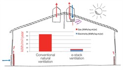 than wastefully pre-heating the incoming air with radiators or heating elements.
 - Pre-heating the incoming air in this way adds to the overheating problem in a typical classroom, which means that the ventilation rate has to be higher than minimum ventilation. The extra incoming cold air then requires more pre-heating, wasting further heating energy.
The high energy bills associated with natural ventilation have led to many in the industry using mechanical ventilation with heat recovery as an alternative. However, we can see that e-stack still saves energy with comparison with MVHR. The reasons for this are:
- MVHR causes the room to overheat in winter,
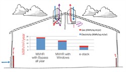 requiring increased ventilation rates and therefore fan power.
 - Even when MVHR is combined with opening windows the fan power used in the winter and as a summer boost means that the e-stack ventilation option is the lowest energy.We have also run comparisons for buildings with different U-values. For example for buildings with Passivhaus U-value standards e-stack is still the lowest energy because of its lower fan power and the ability to operate at minimum ventilation for a larger proportion of the time during the winter months.
For most building types e-stack ventilation is the lowest energy option in the UK. By downloading the IES model on the right, you can see how significant this energy saving might be for your building.
How to model your own building
Download and open the model. By default the model contains ‘Vista’ files for a Manchester TRY weather file and Passivhaus and Good Practice U-value standards.
In order to run your own simulations there are four main parameters to change; the occupancy of the room eg. number of people, the U-values, location and the ventilation strategy.
- Occupancy – This can be changed in Building Template Manager. By default the occupancy is set to the profile ‘School Week Accurate’ which runs 9-5pm with 10 minute breaks and an hour for lunch.
- U-values – the construction database contains constructions with U-values for Passivhaus, Good Practice, Typical Practice and Minimum Part L. These can be applied to your building as necessary.
- Location – This can be set to any location based on IES standard weather files. As standard the building is in Manchester.
- Ventilation Strategy – the 3 possible ventilation strategies are MVHR, e-stack and conventional natural ventilation. All of these can be found in ApHVAC. As standard the ventilation will be applied to the north facing, middle storey classroom, 1_N.
- The ApacheSim simulations can now be run.
- The outputs should now be imported into the excel spreadsheet to post-process the fan power and to generate a graph of energy consumption.
- For Conventional Natural Ventilation it is required to output ‘Room Heating Plant Sensible Load’ and ‘ApHVAC heating coils load’. This sum of these 2 numbers is the total heating energy demand of that room.
- For all other ventilation modes the outputs required are ‘Dry Bulb Temperature’, ‘Air Temperature’, ‘Heating Plant Sensible Load’, ‘ApHVAC Air Supply’ and ‘Natural Vent’. The formulae within the Excel sheet will use these numbers to calculate the required fan power and heating energy required for the room.
Please click to download the Breathing Buildings IES modelling for natural ventilation.